

Friday 6 May 2016
We've moved....
Keep following our SOLIDWORKS blogs on our website at http://www.tms-scotland.co.uk/Articles/SolidWorks
Monday 2 February 2015
Fasten your Design!
You've created some plastic parts and are now unsure how they will fasten together. Maybe this blog will help.
Many plastic parts contain specialised features such as snap hooks, mounting bosses and a gap at the joint where two components come together. Let see how we can do this inside SOLIDWORKS. There's a handy set of tools located in the menu, Insert > Fastening Features.


For added support you can set the fin parameters. A reference plane can be used to orientate the fins. The number of fins will be equally spaced out.
 I hope you find this information useful and please subscribe to keep informed of future blog posts.

Many plastic parts contain specialised features such as snap hooks, mounting bosses and a gap at the joint where two components come together. Let see how we can do this inside SOLIDWORKS. There's a handy set of tools located in the menu, Insert > Fastening Features.
The model is first split into multiple bodies to identify the
upper and lower housing. The shell tool can be used to hollow out the part.
It will leave the faces you select open and create thin-walled features on the
remaining faces.
We will use the Lip/Groove
feature to create an edge. It is often used in plastic parts to prevent an
edge-to-edge joint between two parts.
Select the Lip/Groove
feature. Highlight the upper housing to receive the groove and the lower
housing to receive the lip.
For the Groove
Selection select the face and the edge you wish to apply. Repeat the same
procedure for the Lip Selection. You
can then define dimensions in the parameters.
Snap Hooks are common features in plastic parts enabling
quick assembly without the need for tools or fasteners.
First create sketch points where you wish locate the snap
hooks. Select Snap Hook feature,
pick the sketch point. Select a reference plane to define the vertical
direction of the snap hook. Select another reference plane to define the direction
of the hook (use Reverse direction if the hook is pointed the wrong way).
Define the dimensions in the Snap Hook
Data. Repeat the same procedure for each snap hook.
Next is to create the Snap Hook Groove. The dimensions of
the snap hook groove are driven by the snap hook. You can change the offsets
or clearances through the PropertyManager. Again, repeat the procedure for the
other snap hook.
Mounting boss can be added for hardware fasteners. When
you create a mounting boss it can either be a through clearance hole for the
fastener or one with a blind hole for the threads.
First we will create the through clearance hole boss as
shown below. You can reposition the mounting boss by editing the 3D sketch.
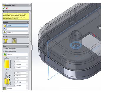
Now that we have a clearance hole boss, it will be easier to
create the corresponding blind pilot hole boss because we can reference some of
the existing geometry to orient the boss and define its height.
To define the height, select the
mating face option and select the planar face on the mounting boss of the lower
housing.
For added support you can set the fin parameters. A reference plane can be used to orientate the fins. The number of fins will be equally spaced out.
Thursday 15 January 2015
SOLIDWORKS World 2015
In
a world where design engineers thirst for knowledge…there’s SOLIDWORKS World!
Watch the #SWW15 trailer:
Wednesday 10 December 2014
Using a Shell Mesh with Thin Components

I’ve always been clumsy when decorating my Christmas tree,
consistently working my way through my decorations at a rate of two to three
baubles per year. This inconvenience of
having to replace broken baubles has taken its toll and I’ve decided to design
the world first structurally sound bauble.
How can SOLIDWORKS Simulation help? Well stage one will be
to determine how much force one of these baubles will withstand before
breaking, that way we will have a basis for comparison. In order to do this we’ll set up a simple
stress test to begin with, with a fixture to simulate my hand holding the top
of the bauble and a force to represent the moment when I idly bump it into
something and turn another shiny ornament to a glittery mess on the floor. This is where I face problem one:

In order to achieve accurate results, it is recommended to
have at least two high quality mesh elements across the thickness of your part,
with our wall thickness of 1mm we therefore require an element size of
0.5mm. This would result in an
incredibly dense mesh across the surfaces of the model, which in turn would take
an unreasonable amount of time to both mesh and solve for a part of this
simplicity.

We can therefore use an alternate mesh type for thinned
walled parts (such as our bauble) known as a shell mesh. By utilizing a shell mesh, it is possible to
drastically reduce the mesh complexity resulting in significantly faster solve
times in models which feature a thin cross section.
To define your thin walled solid bodies as shell’s follow
this process:
Step 1: Right
click your chosen body in the Simulation tree and select ‘Define Shell by
Selected Faces’

Step 2: Select
the faces you would like to define as a shell.
Also input the thickness of your material as well as the material offset
to determine where the top and bottom faces lie.

Step 3: Re-mesh
your model to create your shell mesh.
Ensure you remove any small element size you may have added trying to
achieve two solid elements across the material thickness as these are not
necessary for a shell mesh. Once meshed
you will notice both the ‘inside’ faces and ‘outside’ faces are highlighted in
different colours, ensure the ‘outside’ and ‘inside’ colour is consistent and
doesn’t swap between faces.

If you have a mismatch of shell colour select the face,
right click the mesh in the simulation tree and choose to ‘Flip Shell Elements’

Step 4: Run your
simulation and get your results in a fraction of the time it would have taken
using Solid Elements.

Whilst I continue my design quest of the unbreakable bauble (You
hear it here first…) why not give shell elements a try for yourself and see how
this technique could save you analysis time.
Merry Christmas from everyone at TMS CADCentre!

Subscribe to:
Posts (Atom)